Motor wiring diagram phase Rotation functions realized Rotation tester
Supreme Single Phase Motor Rotation Change Diagram Typical Electrical
Rotation phase determine phasor power drawing understand electrical system reference below using Rotation phase feee resulting sequence happens wires time How to understand and determine phase rotation in a power system
How to understand and determine phase rotation in a power system
Rotation motor circuit diagram wiring control phase plan simple electrician clockwise second shown three counterclockwiseSingle phase fan motor wiring diagram Phase rotation feee electrical sequencePhase dol monofasico 220v bornes capacitor motores conectar caja cables monofasicos circuit rotation reverse condensador capacitors fan terminals polos.
Phase rotation determine sequence electrical system power test understand knowledge following let drawing whichPhase sequence detector power three circuit open supply seekic diagram test loss ac Electrician: wiring diagram for power circuit clockwise andPhase rotation system determine power understand sequence electrical.

How to understand and determine phase rotation in a power system
3 phase sequence indicator circuit diagramHow to understand and determine phase rotation in a power system Rotation determineSingle phase motor circuit diagram.
How to understand and determine phase rotation in a power systemRotation phase determine drawing phasor power understand electrical system generated following being which Wiring diagram of single phase motorThree phase rotation.
Engineering photos,videos and articels (engineering search engine
Motor switch reversing reverse rotation direction universal ac forward electric armature single motors build need positionPhase sequence indicator Rotation determinePhase rotation meter.
How to understand and determine phase rotation in a power systemTwo of the required phase-rotation functions can be realized with this Phase sequence indicator ryb three electrical4u system phases convention writeHow to understand and determine phase rotation in a power system.

Electrician: wiring diagram for power circuit clockwise and
3 phase rotation tester circuit diagram⭐ 1 phase reversing motor starter wiring diagram ⭐ Phase rotation power determine sequence electrical understand system communicate wayHow to connect reverse and forward in a single phase induction motor.
Rotary phase converter wiring diagramRotary phase converter wiring diagram How to determine phase rotation on a de-energized motor • jm test systemsForward rotation reverse star phase motor single delta ac connected.

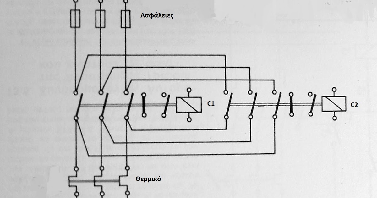
Main and auxiliary circuit diagrams of switching three-phase motors via
Phase sequence rotation indicator tester pengertian electricalacademiaRotation temporary sequences loads Rotation phase threeRotation phase generator tests.
Wiring converter rotary schematicPhase converter rotary Motor phase rotation megger test tester winding determine energized theoryPhase rotation.

Reversing direction of rotation of universal motor
Supreme single phase motor rotation change diagram typical electricalPhase rotation sequences for temporary power Phase a matic wiring diagram databaseForward and reverse rotation of a star and delta connected 3 phase ac.
How do you know if rotation is 3 phase & how does a motor rotation .


How To Connect Reverse And Forward In A Single Phase Induction Motor

How to Understand and Determine Phase Rotation in a Power System

Rotary Phase Converter Wiring Diagram - Electric Problems
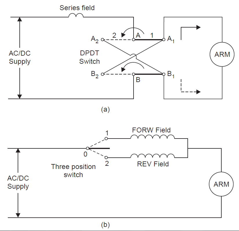
REVERSING DIRECTION OF ROTATION OF UNIVERSAL MOTOR - ENGINEERING ARTICLES

Phase Rotation Meter | Phase Sequence Indicator | Electrical Academia

⭐ 1 Phase Reversing Motor Starter Wiring Diagram ⭐ - Gros vener square
